Working with Volume Textures in Unreal Engine 4 by Ryan Smith

Watch and share 2019-11-21 00-51-29 GIFs by Ryan Smith on Gfycat

Volume Texture assets are a new feature that shipped with Unreal Engine 4.21. It flew under the radar because the release notes don't mention the addition of the new feature. Fortunately, there is documentation on how to create and use them. They may not seem very useful at a glance, but they have numerous applications. I'll walk you through how to create them and show you some examples of their use.

But before we get into it, let’s take a moment to learn what a volume texture is. A normal texture is a two-dimensional grid of pixels. It has a length and a width. A volume texture has a third axis, which you can think of as a "stack" of textures on top of each other. So, if you defined a volume texture to be 32x32x16, it would consist of 16 32x32 pixel images packed on top of each other. You can put whatever images you want into a volume texture as long as they all have the same length and width dimensions. This is visualized in the image below - The transparent green represents the volume texture, and the “slices” are visualized as a “pseudo volume texture” next to it.

 
GIF taken from Ryan Bruck’s blog post.

GIF taken from Ryan Bruck’s blog post.


In this article, I’m going to go over how to create volume textures and show you how to apply them in various ways.

Creating Volume Textures

Pseudo Volume Textures

Creating volume textures first requires you to make a Pseudo-Volume Texture. These are 2D textures that store “slices” of a volume in rows and columns. This is visualized in the GIF below where I am creating a pseudo-volume texture which stores the density information of a sphere. The pixels that are inside the sphere are colored white, and the pixels on the outside are colored black. They are then arranged into a 2D texture that holds 3D information, hence the “Pseudo” name.


Ryan Brucks from Epic Games has a series of blog posts all about pseudo-volume textures and authoring them in UE4. I recommend reading up on Authoring Pseudo Volume Textures. There is plenty of information there that he explained very well, and I’ll be repeating some of that information in this article.

One of his posts I do want you to check out is the one on how to generate tiling noise textures. The process outlined in his post from 2016 was before the volume texture asset was available, and the method to generate and sample pseudo-volume textures was quite involved. Unfortunately, It was the only way to do it at the time. Fortunately, with the advent of Volume Textures, we get to cut out all the custom code and extra material functions that needed to be written in order to create and sample seamless tiling 3D Noise textures! It’s so much easier now. Lets explore.

Enable Volume Textures

As of 4.23, you have to enable volume textures by editing your DefaultEngine.ini file. So go to your project directory’s Config folder, find DefaultEngine.ini (if it doesn’t exist, create it). Then navigate to the Render Settings section (if you don’t see that section, you can create it) and add “r.AllowvolumeTextureAssetCreation=1”. I have an example below.

[/Script/Engine.RendererSettings]

r.AllowVolumeTextureAssetCreation=1

Create the Noise Material

For this example, let’s render some tiling Voronoi noise with 6 octaves. High quality Voronoi Noise is notoriously expensive at ~600 instructions, so it’s the perfect type of noise to cache to a Volume Texture.

Voronoi Noise.PNG

Create a new unlit material and set it up like the above image. The Noise node’s parameters can be seen in the bottom left hand part of the image.

Create a Render Target and a Blueprint for Rendering to It.

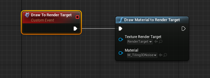
Next, create a Render Target Asset and set its size to 4096x4096 and the Render Target Format to RGBA8. Then create a Blueprint Actor and in the Event Graph, create a Custom Event and name it something like “Draw To Render Target”. Select the event node and enable “Call In Editor”. Add a “Draw Material To Render Target” node and wire it to the custom event. Reference your newly created Render Target asset in the “Texture Render Target” property, and then reference your Noise Material in “Material” property.

Draw to Render Target.PNG

Compile the blueprint and drag it into the scene and click the “Draw to Render Target” button that you should now see in the “Default” category of its Details. You should see your material drawn to the Render Target asset. If you don’t, you might have to open the Render Target asset and disable the “Alpha” channel to see what’s in there.

Generate the Volume Texture

Next, Right-click the Render Target asset and choose “Create Static Texture”. This will make a Texture object in the same folder as your Render Target asset. This “static” texture is what we use to generate the volume texture. Right-click on that bad boy. If you edited the “DefaultEngine.ini” file properly, you should see an option near the top that says “Create Volume Texture”

Doing so will make a Volume Texture asset. Name it something cool like “VT_WorleyNoise” and wait a few seconds as it processes. Open up the Volume Texture and Enable “Compress Without Alpha” since we don’t have one. This will reduce the memory footprint of the asset. Next, go to View>Viewmode and enable “Trace Into Volume” This will create a visualization of your Volume Texture that you can rotate around and play with.

Watch and share 2019-11-17 00-15-01 GIFs by Ryan Smith on Gfycat

2019-11-17_00-06-14.png

Create a Material for Testing the Volume Texture

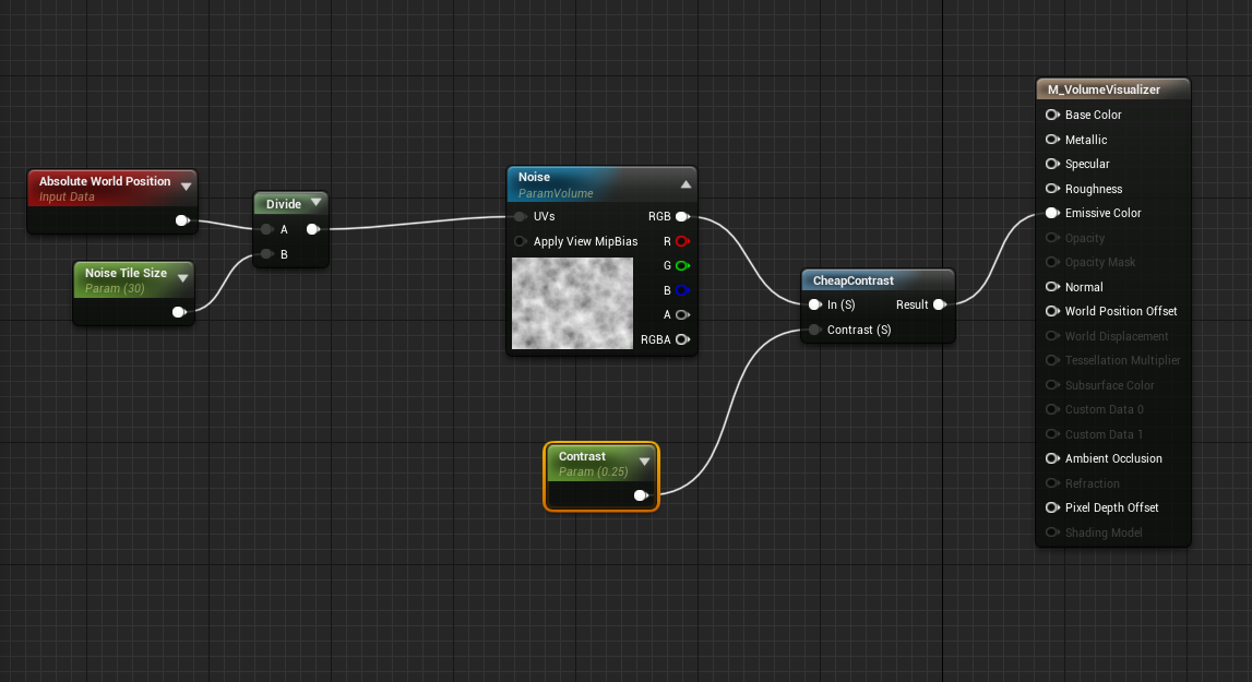
Now that we’ve got a volume texture made, lets create a material to test it out. In order to sample a volume texture, you need to bring out a special type of sampler node called a Texture Sampler Parameter Volume. Remember, since it’s a volume texture you’ll need a float 3 for the UVs. I typically use World Space divided by a “Tile Size” parameter.

visualizer.PNG

Watch and share 2019-11-17 16-52-56 GIFs by Ryan Smith on Gfycat

When dragging the object through the scene, you’ll see the 3D change since we’re sampling from World Space. If you don’t want that to happen, sample from “Local Space” instead.

Caching the Voronoi noise to a volume texture saves us around 600 instructions for the cost of around 10MB at a 256^3 texture size. If your budget is tight, setting the maximum texture size to 128 brings the resource cost down to under 1.2MB for not that much visual difference.

Bake some Curl Noise

Don’t stop with Voronoi Noise! I also like to bake vector noises such as Perlin Curl into a 3D Texture as well. These types of vector noises store directional information that can be useful for warping UVs

Watch and share 2019-11-18 22-28-09 GIFs by Ryan Smith on Gfycat

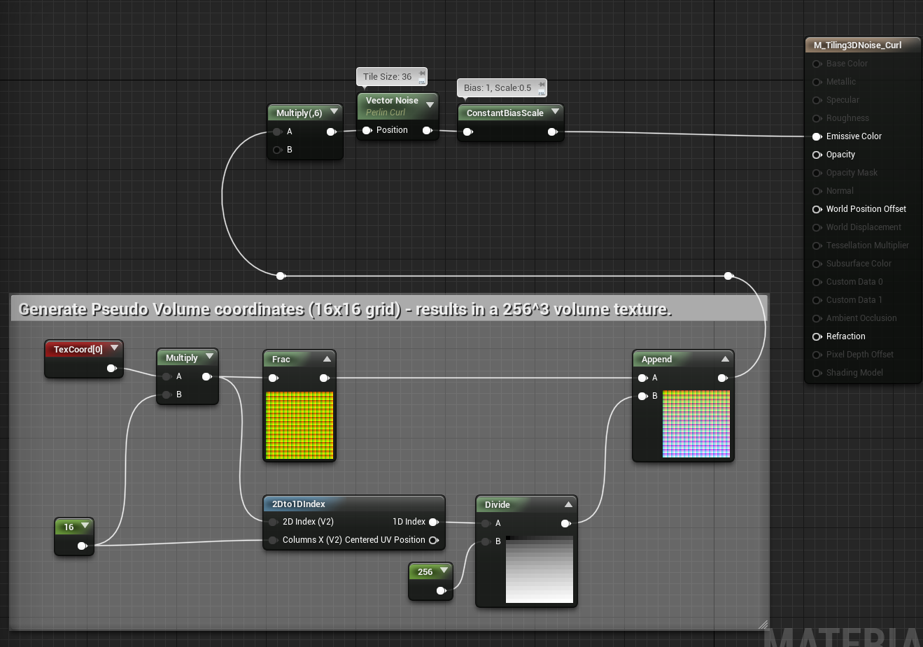
curlnoise setup.PNG

Above is a 3D Texture of Perlin Curl Noise - I used the Vector Noise node to generate this. Getting it to tile is a bit tricky, though. I had to multiply my UVs by 6 and use a Tile Size of 36 on the Vector Noise node. You then have to remap the values into the 0 to 1 range when you bake it out. When sampling from this volume, remember to map the values back into the range of -1 to 1.

Applications

Now that you’ve got all these beautiful volume textures at your disposal. Let’s take a look at some of their applications.

Visual Effects

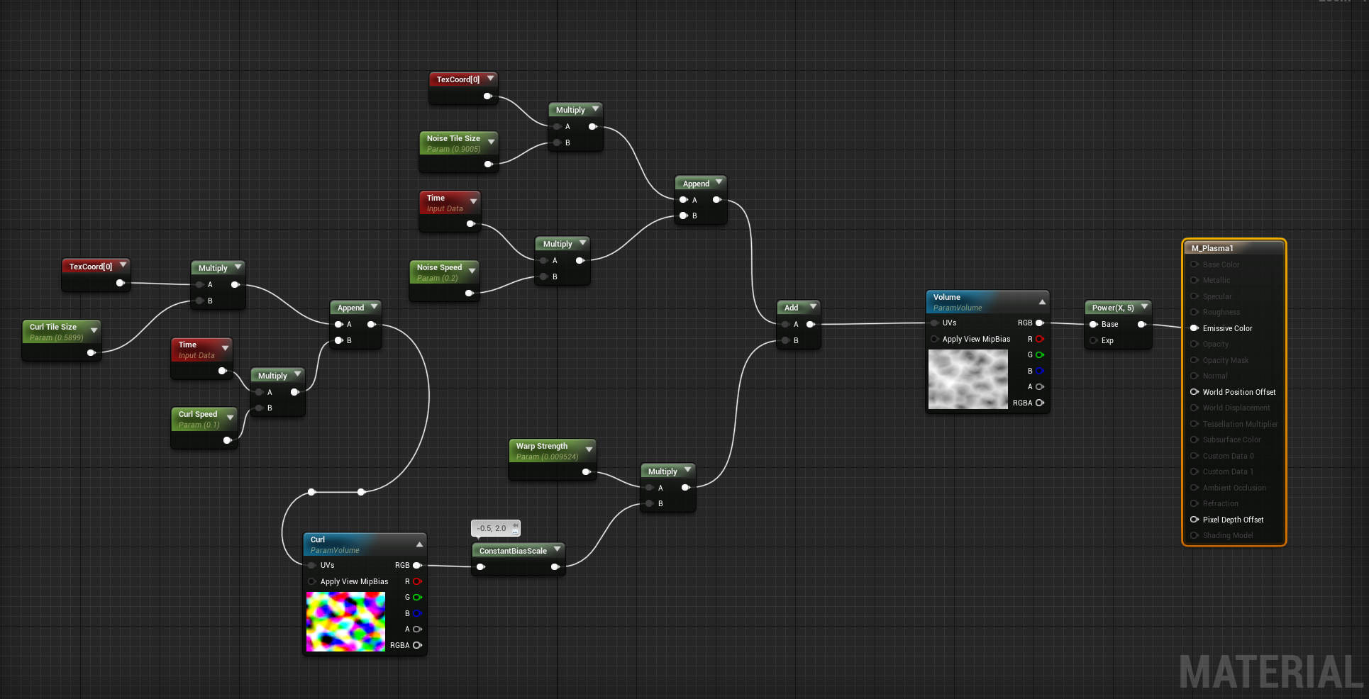
I love to sample these textures with a mesh’s UV Coordinates and append a Time term to the W coordinate to “push” the UVs through the Volume texture.

You can see the setup in the image below and the resulting visuals to the right. It creates a pretty cool animation that would be very difficult to recreate with 2D Textures.

example1.PNG
 

Watch and share 2019-11-20 18-57-52 GIFs by Ryan Smith on Gfycat

We can further improve visuals by sampling our Curl Noise using the same technique and using it to warp the UVs of the original noise texture to create more interesting effects. Combining multiple noises and multiple warps can produce a whole variety of visuals.

example2.PNG

Watch and share 2019-11-20 18-49-29 GIFs by Ryan Smith on Gfycat

The above shaders were all created using the techniques above with some simple adjustments to UV size and warp strength. You can go even further by panning the textures on their U or V axis. This is how the fire in the above GIF was created. It looks quite natural and it’s hard to spot any repeating elements since all of the textures are panning on multiple axes at different speeds.

Volumetric Fog

Adding a bit of texture definition to volumetric fog is another great use case for volume textures. Without the textures themselves, you’d have to use the noise nodes in your materials which can be very costly. Baking them down simplifies the cost of the shader a great deal and allows more complex effects without becoming prohibitively expensive to use. We used these all over the place on Borderlands 3.

Watch and share 2019-11-21 00-33-55 GIFs by Ryan Smith on Gfycat

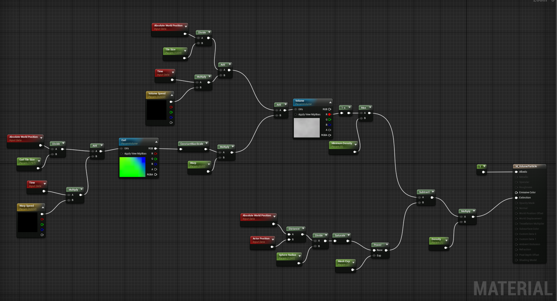
In the above image, I’m using a shader that samples a warped Voronoi noise with a 3D spherical mask for use with volumetric fog. The scene was taken from the Multi-Story Dungeons kit that you can get on the UE4 Marketplace. I applied the shader to a simple sphere static mesh, which is then used to render a volume into the scene. Documentation for using Volumetric Fog can be found here. Other examples can be found on Ryan Bruck’s blog post titled UE4 Volumetric Fog Techniques. That post is a couple of years old now, and you can see the way things had to be done before the volume texture asset was a thing.

volumetric fog example.PNG

Don’t forget to set your material domain to “Volume”

Clouds

Ray Marching is an incredibly complicated and expensive technique, but it can be used to render beautiful cloudscapes like those seen in Horizon Zero Dawn, Red Dead Redemption 2, and a few other open-world games.

In fact, the technique in the video above is not possible without using a few different tiling volume textures. For more information on this technique, you can check out their paper. They also have a detailed guide on how to create this in GPU Pro 7 (Chapter 4). If I get some time, I hope to walkthrough how this effect can be accomplished within UE4.

Final Thoughts

Volume textures are easier than ever to create and work with in the Unreal Engine. With the addition of Volume Texture assets and the tools that automatically create them from Pseudo Volume Textures, you' can get up and running with them quicker than ever. I encourage everyone to integrate these textures into your visual effects and environment art pipelines. Obviously, all of the applications cannot be covered in a single post, but I hope to how everyone ends up using these. Thanks for reading!

Ryan

A Practical Approach to Creating Glass Materials for Physically Based Rendering by Ryan Smith

Watch 2019-03-24 23-05-39 GIF by @virtuosic on Gfycat. Discover more related GIFs on Gfycat

A colleague of mine recently asked me how i’d go about creating glass, so I figured I would make a walk through. We’ll start by making some grunge textures in painter and then we’ll import them into UE4. This walk through isn’t intended for beginners. As such, i’ll be skipping over some details that i’m assuming you already know.


Making the Grunge Textures

The grunge texture we’re going to make will act as a mask between our glass sub-material and our dirt sub-material. This is probably the most important part of the process because without decent grunge textures, our glass won’t look convincing. Anywhere where the grunge is applied will increase roughness, opacity, and base color resulting in the appearance of dirt on the glass.

Don’t pick a random noise or grunge to use for the dirt map. Find some textures that make sense to use on a window pane that’s exposed to the outdoors. Tell a bit of a story with it. Did the window get dirty and splattered before someone came by and tried to wipe it down? Would you see the evidence of those wipes and leaks? How about moisture? If the window was exposed to morning dew, humidity, and rainstorms, you’d definitely see some of that. Those were the questions I asked myself before starting to make some of the textures.

In the GIFs below I’m using Substance Painter’s stock noises because they work really nice for what I need. I start with a Dirt1, then add in Grunge Leak Small and then subtract Grunge Wipe Brushed to give it the look like someone tried to clean it off at some point. I then use a Perlin Noise to subtract some detail and break up the tiling a bit. I then add on some Moisture Noise. Finally I adjust levels a bit and finish up with a Sharpen. I did a similar process for the secondary grunge using similar maps. You can see that on the bottom right.

Watch 2019-03-24 19-08-14 GIF by @virtuosic on Gfycat. Discover more related GIFs on Gfycat

Watch Grunge00 New GIF by @virtuosic on Gfycat. Discover more related GIFs on Gfycat

To preview these in painter, i have a really simple setup of just two layers. Before you start, navigate over to the Shader Settings and set the shader to PBR Metal Rough with Alpha Blending. This will allow you to preview the mesh with transparency. I’ve also loaded in a flat plane oriented to the X axis for my preview mesh.

The Base glass layer has the following properties

BaseColor - 0.01 (Grayscale)

Roughness - 0.0

Metallic - 0.0

Opacity - 0.5

The Dirt layer only has 3 channels enabled and their properties are as follows:

Base Color - 0.15

Roughness - 1.0

Opacity - 1.0

I then add a black mask to the Dirt Layer and build the above textures directly in the mask stack. Result should look something like below.

If you want to create Opaque glass, simply set the opacity of the glass base to 1.


Watch 2019-03-24 21-20-20 GIF by @virtuosic on Gfycat. Discover more related GIFs on Gfycat


Building the Glass Shader

Time to pull the textures we made into Unreal and build a shader with them.

Lets first think about the properties which are relevant to physically based lighting of a completely flat pane of glass . We’ve got Base Color, Roughness, and Opacity. We don’t care about Metallic, since glass isn’t metallic. I don’t care about the normals either, since we’re building the shader for typical glass that doesn’t have bumps and grooves or warps. I’m also going to use the Spiral Blur function that comes with the unreal engine, and as a consequence of that decision, i won’t be able to use refraction, so i’m not going to worry about that for now. I can drive all of the effects above through a single packed texture map that contains the two textures I created above. One other important assumption to make here is that that this shader is designed to be used on a flat plane mesh. Adding this constraint enables us to add some cool features that will help improve its versatility.

So, I’ve created a shader. I have Blend Mode set to Translucent, Shading Model set to Default Lit and Lighting mode set to Surface Forward Shading. A warning here, using the surface forward shading is the most expensive lighting mode for translucent shaders because it calculates lighting for each light that’s hitting it, rather than using a deferred method. It also takes forever to compile so i hope you’ve got some patience. If you don’t have patience you can always just set blend mode to opaque to act as a “preview” until you need to swap back to translucent to test out the spiral blur. I’ve also enabled “Use Material Attributes” because i prefer to work that way when working on a shader that is blending multiple sub-materials.

The shader we’re going to build consists of 5 elements; We’ll first create the Glass and Dirt sub-materials just like we did in Substance Painter. We’re going to then create the grunge map expression that is the most involved part of the shader. After that we’ll hook up spiral blur and call it a day.

The final material at a glance. You can use this image to get your bearings when looking at the closeups below.

Lets first look at the Glass and Dirt sub-materials. This is a great place to start. I use Make Material attributes to set up our sub-materials because it’s just so much easier to work with when creating a shader that’s blending between two or more of them. If i didn’t use Material Attributes i’d have to blend all of the relevant attributes which would create a spaghetti node network. This method lets me keep it pretty clean.

Glass and Dirt Sub-materials

After the Glass and Dirt are set up to blend, I start to craft my Grunge Map expression. This is made up of a block of code that samples the packed grunge texture twice. The first texture (the one on top of the graph) is sampled with a slight bump offset to give the illusion of thickness to the glass pane. The second texture doesn’t have this effect. Both samplers have independent UV Tiling controls and scale based on the actor’s scale. This is accomplished by multiplying the coordinates by the Object Scale node. I’ve also implemented some functionality that you can see near at the beginning of the graph which adds a random offset to the texture coordinates whenever it is dragged 32 units in either axis in world space. This will help reduce obvious repetition in the texture in the event the planes are placed adjacent to each other. After I sample the textures i multiply them by a grunge intensity to help hone in the look i’m going for.

Grunge Map Sampling and Bump Offsetting

The inverse edge mask is a great way to break up the glass pane from the middle out to the edges. It’s just an easy tool to add to the box. You can see it’s effect bottom right.

Inverse Edge Mask to help break up glass panes if needed.

Watch 2019-03-25 00-38-25 GIF by @virtuosic on Gfycat. Discover more related GIFs on Gfycat

The mask adjustments block is a place where i add a bias so i can sort of control a minimum amount of grunge. I then multiply it by a “Master Intensity” which is essentially a master knob for the grunge intensity that happens after all the other values are nailed down. I have a bunch of saturates here to act as a sort of check on user input as well as keep the values in the range of 0-1. They’re practically free to use on modern hardware so it’s not too shitty to use them… although I may be able to get rid of one of them below but i got lazy.

Mask Adjustments

The last part of this is setting up the Spiral Blur. This expensive node ships with UE4. It samples the scene beyond the glass pane a shit ton of times and then blurs it in a spiral, which when used right gives some pretty great results. In our case, we’re multiplying the strength of the blur by our roughness parameter since it acts as a pretty good representation of our grunge mask. I’ve also got a custom Distance Mask that’s derived from Scene and Pixel depth. Subtracting Pixel Depth by Scene Depth gives us the distance of the pixel BEHIND the glass to the pixel on the glass plane. This will give a falloff to the blur based on that distance. After that setup, I follow the node’s instructions and hook the Result into Emissive Color and add the “Scene Color clamp to 0” into the opacity chain to finish everything off.

Quick tip: Use the Get and Set Material attribute nodes to quickly modify their attributes without using the big clunky “Break” material attributes node.

After all is said and done, you should have all the parameters you need to tweak yourself a cool lookin’ glass material! Try scrubbing Master Grunge Intensity back and forth. It’ll show you the range you can get from your grunge maps. Also notice the effect of the spiral blur as the grunge density increases and decreases. It does a great job at blurring the scene behind the glass when the grunge gets thick.

Watch 2019-03-24 23-02-05 GIF by @virtuosic on Gfycat. Discover more destiny2 GIFs on Gfycat

Try adding your own features or tweaking the shader to get some cool results. I really hope this walk through helps you in some way! Cheers.

Fluid Morph by Ryan Smith

In my previous post I spoke about how to make curl fields to quickly approximate the effects one would see during a fluid sim. The effect works good enough if you’re only looking to sim around a second or so into the future, but it quickly breaks down after that. In order to create something a bit more realistic, we have to take two important properties of a fluid sim into account: Viscosity and Diffusion.

Viscosity is actually really simple. You just have to blur the vector field that you’re warping your image by. In our case, it’s the curl field that we learned how to generate in the Curl Fields post. Diffusion is also a blur, but it’s applied to the areas of the warped texture based on the intensity of the vector field we’re using to warp the image. To achieve a good result, we run about 6 iterations, blurring the textures every step. The strength of the blur that is applied to the vector field is the Viscosity value, and it is multiplied by the “Warp” strength. Diffusion is the strength of the blur that is applied to the image we’re warping, which is also applied every step. In the GIF below, you can see how the portions of the texture that are being warped gets blurred out a bit - this is the Diffusion in practice. Later in the GIF you’ll see the curls and warping “relax” a bit - this is the effect of viscosity.


Watch BxEOHyL8Cx GIF on Gfycat. Discover more related GIFs on Gfycat


Below is a break down of the node, which you can now download for free on substance share.

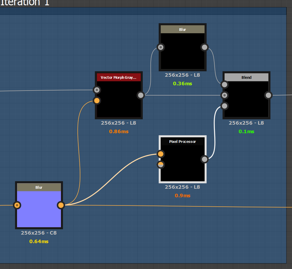
You can see here that the node graph is pretty basic - it’s just 5 iterations of the same node expressions which you can see below.

You can see here that the node graph is pretty basic - it’s just 5 iterations of the same node expressions which you can see below.

An example of one of the iterations. We run a vector morph with a blurred version of the curl map (The blur amount is Viscosity). Then we blur the result by the divergence mask (See below) - and that gives us our diffusion. Then we pass it along to …

An example of one of the iterations. We run a vector morph with a blurred version of the curl map (The blur amount is Viscosity). Then we blur the result by the divergence mask (See below) - and that gives us our diffusion. Then we pass it along to the next iteration.

Inside the Pixel Processor node, i calculate absolute divergence. All this does is calculate the absolute slope of the x and y components of the normal map, then add them together and divide by the inverse of the texture size. This gives me a nice m…

Inside the Pixel Processor node, i calculate absolute divergence. All this does is calculate the absolute slope of the x and y components of the normal map, then add them together and divide by the inverse of the texture size. This gives me a nice mask where the white values correspond with areas of high fluid movement, where areas of no fluid movement remain black. To be honest this might be overkill and there could be an easier way to approximate this, but whatever.

This mask is used to mask the diffusion blur - so the more intense the vector field is, the more diffusion happens!


So yeah this node is cool for generating some organic swirly things which is just another tool in the tool belt. Enjoy a couple quick examples below.

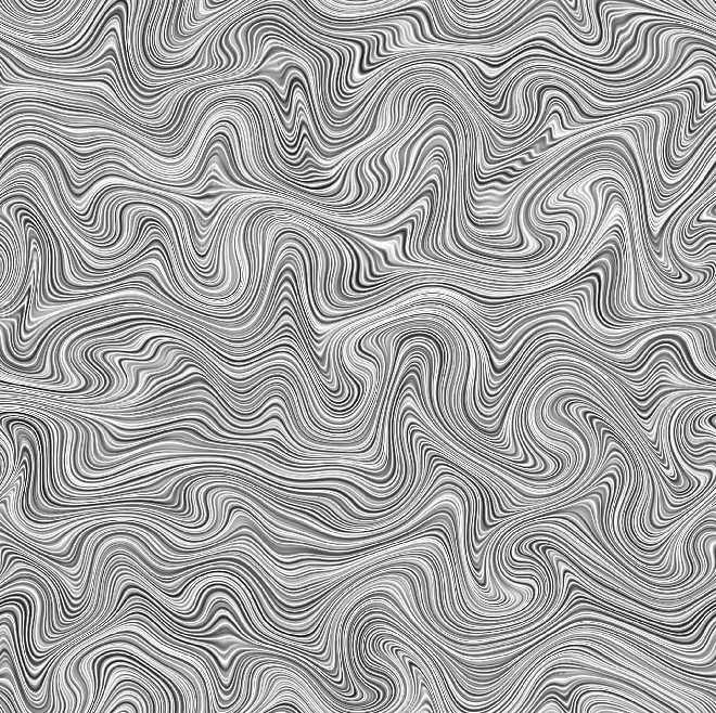
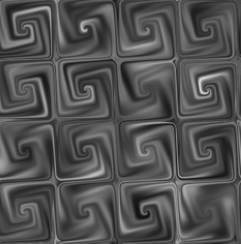
Example of using curl noise to add interesting decorative patterns to a tiling floor texture.

Example of using curl noise to add interesting decorative patterns to a tiling floor texture.

Anisotropic Noise Fluid Warped by Gaussian Noise

Anisotropic Noise Fluid Warped by Gaussian Noise

Thanks for reading, and Happy Holidays!

Curl Fields in Substance Designer by Ryan Smith

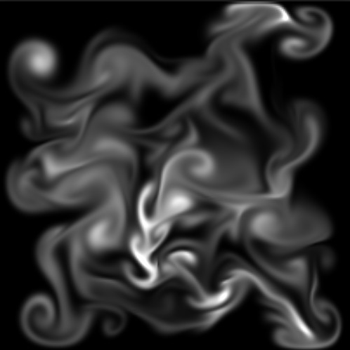
I’m writing this blog-post because during my google research, I couldn’t find any hits that helped me achieve fluid like warping of textures - similar to what you’d get by running a Navier-Stokes fluid simulation.

Example fluid sim from Google Images.

Example fluid sim from Google Images.

If you’re unfamiliar with fluid simulation, Jamie Wong gives a pretty good rundown of it on his blog. You can open that page and see a fluid sim right away, and even use your mouse to influence it.

My goal here is to use Substance Designer to create an easy-to-use node that gives us those curly vortex shapes that happen naturally in these fluid simulations. Unfortunately, the current off-the shelf tools that come with Substance Designer don’t give you the ability to get those nice vortex shapes without some setup. You’re able to warp images, but they often end up pinching or stretching in ways that don’t look like fluid at all.


Watch 2018-10-26 01-04-51 GIF by virtuosic on Gfycat. Discover more related GIFs on Gfycat

Typical result of using Vector Morph derived from a Gaussian noise. Notice the pinching and stretching that happens due to divergence in the vector field.


At first, I tried recreating the Navier-Stokes equation directly inside Substance Designer and succeeded (sort of), but the node was just too cumbersome since there’s many calculations that need to be done on several components of the simulation’s equation in order for it to look correct. Each calculation of the equation is just one time step, and you’ll need several hundred steps to get a result that’s acceptable. This approach ended up being completely impractical, however it wasn’t a total failure because I came away with the knowledge to achieve what I needed to in a much simpler way.

Before i get into that, i want to spend a moment to talk about what makes a good fluid simulation. This is a long walk, so bear with me. The key is having a non-divergent vector field to advect your texture with. Divergence, in this context, is the measure of how much fluid enters or leaves a given area in a single time step. If more fluid enters than leaves, it has positive divergence, which will eventually lead to pinching. If more fluid leaves than enters, it has a negative divergence, which leads to nasty stretching. A field that has no divergence has the same amount of fluid entering and leaving any given area which leads to a beautiful warping effect with no pinching or stretching. Unfortunately, as I explored the solutions offered to me in Jamie Wong’s post, I realized that creating a divergent free field is easier said than done. Doing so requires calculating pressure from divergence and then using like, 40 - 80 Poisson blurs to generate a nice enough pressure gradient that is then used to create ANOTHER vector field which is subtracted by the previous time step’s velocity field after it has been advected by itself, etc. It gets pretty complicated, but the end goal is to create a non-divergent vector field so that we get those pretty swirly shapes.

In order to cut down on complexity, we can take a step back and think about what’s necessary for us to achieve our end goal. Lets assume that we don’t care about several fluid properties like viscosity or diffusion rate or density for the time being. We also don’t care about variable force, because at the end of the day, we’re not running a simulation, we’re creating a single node that gives us results SIMILAR to a simulation. With that being said, we can just make the assumption that we’ll be using a constant vector field which does not change over time to drive our warping effect. With that assumption, we can just precompute a single vector field, and as long as that vector field is as non-divergent, we’ll get acceptable results.

But… how can I generate a divergent free vector field in Substance Designer? The answer is simpler than you’d think. We use a grayscale height field and calculate it’s curl to create a “Curl Field”. We do this because a Curl Field has the property of being divergent free! Unfortunately, there are no prepackaged tools that creates a Curl Field from a Height Field, but making one is incredibly easy to do, especially if you’re working with a two dimensional vector field.

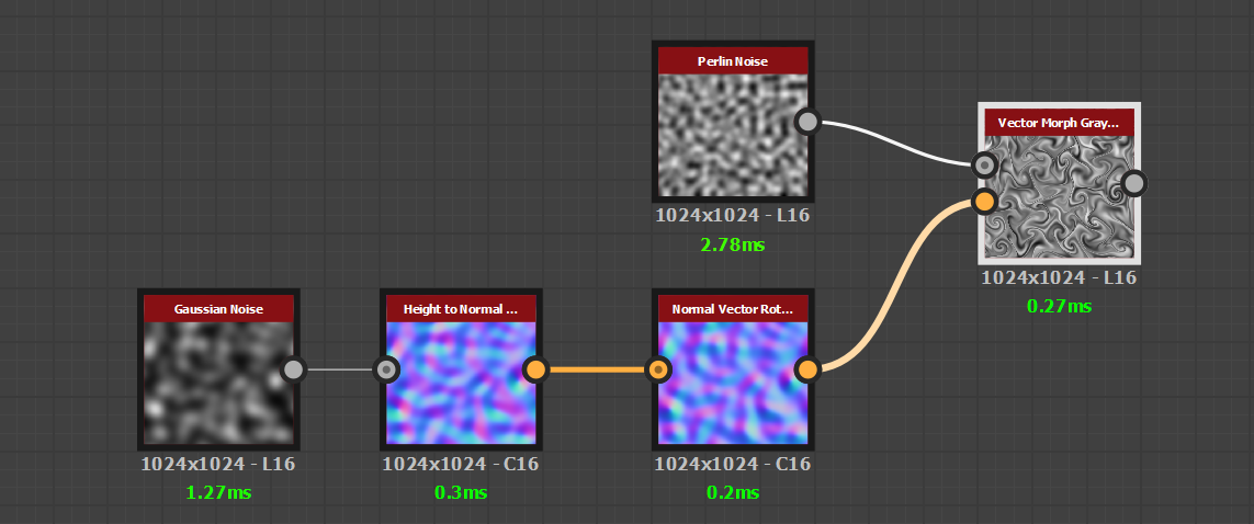
The set up is easy. Grab a smooth grayscale noise like Perlin noise or Gaussian noise. Convert that into a normal map using Height-To-Normal World Units. (this gives a normal map with a nice range). Then use the Normal Vector Rotation node to rotate your normals by -90 or 90 degrees. That’s it. This creates a vector field where, instead of the vectors moving along the slope, it curls AROUND the slope, hence the name “Curl”.


Watch 2018-10-26 22-55-52 GIF by virtuosic on Gfycat. Discover more related GIFs on Gfycat

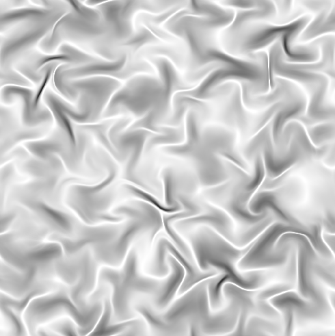
The same Vector Warp as above, but this time it’s being advected by a Curl Field instead.

 
SimpleSetup.PNG

An advantage to this setup is that you can experiment with other weird noise patterns. You can essentially use an HQ Blur on any height field and use the results to generate something usable! Here’s some more examples of some cool shapes.

This should be all you need to get started playing around with creating and using Curl Fields! My next blog post will cover an expansion of this where we use Curl Fields to create a fast “Fluid Morph” node that takes viscosity and diffusion into account. Stay tuned.

Procedural Star Fields by Ryan Smith

It's tough to make a starry-night sky using textures. You either have to use very large textures to get the resolution you want, or you have to use smaller tiling textures, resulting in obvious repetitive patterns. Some people end up using a combination of both which may get the job done at the expense of precious memory.  

The longer you've been doing game development, the more you'll understand that there are countless ways to achieve a desired result. The only difference is what it costs you. Lets take a look at a way to make stars that wont cost you any texture memory. Instead, this method relies on the raw horse power of the GPU, costing us only pixel shader instructions. 

How it Works

The algorithm can be broken down into a few steps. First, generate a grid of UV Cells. Offset the UVs by -0.5 so that the origin is in the center of the cell. Use the cell to generate a radial gradient with a radius of 0.5. Them using a random vector per cell, offset the radial gradient's position and shrink the radius by double the magnitude of the random vector.

To preview the algorithm in action, left click and hold the button down on the below image, and drag your mouse left and right. You'll see the basic steps of the algorithm animate as you move your mouse further to the right of the image.


Below is another shader example, this time with a smaller scale and 8 iterations. Drag left to right to watch the offset happen. You can also enter fullscreen mode by pressing the square bracket button on the bottom left. 


A Small Look at Generating Random Noise

At the heart of pretty much all noise generators is a function that creates pseudo random noise.  The function i'm using in the above examples comes from David Hoskins's awesome Shadertoy example. I use the "hash22" function, where the "22" means that the function takes a 2D value as an input and returns a 2D value. The  below method is how i "look up" random values per UV Cell. There are many different ways to generate random noise, I encourage you to read up on these methods since they're an important step to many procedural effects. 

Making it work in the Unreal Engine

To make the algorithm work in UE4, we need to implement a version of the noise that works in 3D. The above shaders work with 2D, but it's easy to change it to support 3D. All you have to do is provide a 3D coordinate as an input, and make sure you have a 3D cell noise, the rest of the instructions are the same. Thankfully, UE4 has the Vector Noise node, which defaults to the Cell Noise type. 

In Unreal, I apply the shader to a inverted sphere with a radius of 50 units.

Procedural Star function graph. UE4

The above graph can be considered a single iteration. In this post's cover image, i'm using 3 iterations, each one having a different grid scale and brightness. Check out the results below. 

Watch this GIF on Gfycat. Discover more GIFS online at Gfycat.

That's pretty much it!  I encourage everyone to figure out different ways to make use of this effect other than stars. Thanks for reading. 


Creating fBm Noise with the FX-Map Node by Ryan Smith

The FX-Map is the muscle behind many of the powerful nodes that come with Substance Designer. It's used in pretty much all of the nodes that take an input and scatter it around, like the Tile Sampler and Splatter nodes. Some people use it to create custom scatter behaviors, but I mostly use it for generating noise patterns, so that's what i'm going to talk about in this post. But first, lets look at what Allegorithmic says about the FX-Map so we can all get a baseline understanding of it.

Substance Designer_2018-07-15_01-13-18.png

From Allegorithmic's Substance Designer documentation on the FX-Map:

The most common uses of FX-Maps are creating repetitive patterns, such as stripes and bricks, and noises, such as Perlin, Brownian and Gaussian noises. Noises are particularly useful in creating organic, natural-looking textures like dirt, dust, concretes, stone surfaces, liquid spatters and so on.

An FX-Map graph can contain one or more of the three FX-Map node types: Quadrant, Iterate and Switch. Of these nodes, the one you will likely use most often is the Quadrant, with the Iterate node a close second.

The [Quadrant] node is the prime mover of FX-Maps. It creates the core region quad-tree graph FX-Maps rely on, but it is not displayed as one. Visually, the quad-tree graph is shown in the form of a Markov Chain.

When rendering the FX-Map, the simplified FX-Map graph is ‘unwrapped’ to look like the big tree-like graph. The engine “walks” the entire quad-tree, working top to bottom, then left to right.

FX-Map nodes don’t blindly copy and paste their images. When each image is rendered, any dynamic functions it has are run. The functions affect each image rendered by the node. You can therefore give each individual image a random rotation, or scale factor, or a number of other adjustments.

They then goes on to give a short description of the 3 nodes that you can use inside an FX-Map node:

Quadrant

This splits the image at this step in the graph into four quadrants. This is the most common node type. A chain of Quadrant nodes can create very complex-looking images, as well as intricate patterns.

In fact, Quadrant nodes represent a level—or octave—in a quad-tree graph. FX-Map graphs hide this tree structure by representing each level in the tree with a single Quadrant: every time you connect one Quadrant node to another, you are actually creating a complete tree level. The reason for this 'cheat' technique is to remove the need to represent each node at every level of a tree individually: after just four layers of depth, you would need to use 4 x 4 x 4 x 4 nodes, which is 256 individual nodes! Instead, each Quadrant node "knows" which level it's at in the tree and generates its imagery accordingly.

Iterate

Repeats the image passed into the right-hand connector over the image passed into the left-hand connector by the set number of iterations. This node is most often used with one or more Dynamic Functions graphs to move or rotate the input image in some way at each iteration.

Switch

This takes two inputs and simply switches between one or the other, as defined by its Selector setting. As with the Iterate node, the Selector setting is often chosen by a Dynamic Function.

The FX-Map sub-node that i want to focus on for this post is the Quadrant node. Specifically, i want to focus on it's ability to create Brownian noises. The quadrant lets us create a very similar form of Fractal Brownian Motion, or "fBm" for short. The difference between our noise and traditional fBM noise is that our noise will reuse the same noise map in all of its octaves, instead of resampling the noise with different parameters for each octave.

In my opinion, this technique is incredibly useful for creating realisitc textures. So lets dive into how to make it.

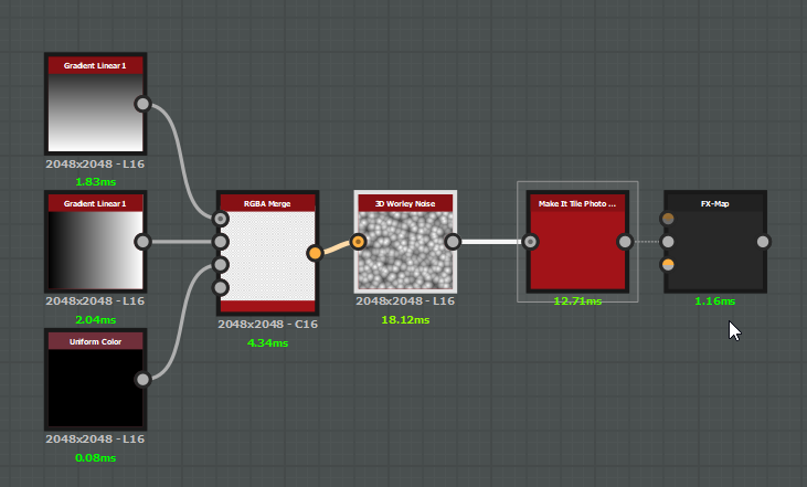
The above images shows the initial setup i'm using. The right image shows the properties of my FX-Map. I'm using two Gradient Linear 1  nodes at different rotations and a Uniform Color (set to grayscale) node set to black. I then plug those into the RGBA Merge which will act as the 3D Coordinates that the 3D Worley Noise needs to do its thing. The 3D Worley Noise's properties are all default other than the scale parameter, which is set to 16.0. I plug that into a Make It Tile Photo (with default settings) to help reduce any seam artifacts that might come about from the fBm generation, which then goes into the FX-Map's Input Image 0 slot. The only thing I've done in the FX-Map at this point is set its Color Mode to "Grayscale". If you plug in a Grayscale input and leave it as Color, nothing will show up. 

Now that the setup is complete, go ahead and double click the the FX-Map node to preview its output, then hit Ctrl+E to dive into the sub-graph. The first thing you'll see is a Quadrant node. Click on it, and go into the properties and set the Pattern mode to "Input Image". If you've done things correctly, you'll see the Input Image 0 as the output preview. Copy paste the Quadrant node and move it underneath the original one, then connect all four of the original nodes' outputs to the new node's input. Then go into the new node and set the Pattern rotation property to 90 Degrees. For each new Quadrant node we add, we'll increment the degrees by 90.  We'll do this 3 more times until we have a 5 node chain. In other words, we'll be creating 5 "Octaves". When you're done, double click the background of the FX-Map to display the global properties of the FX-Map. At the bottom, find the "Roughness" (no, it's not related to the roughness you're probably thinking about) property, and slide it back and forth to get an idea of what the property does. I usually set this value to around 0.5. When your done, your graph should look similar to below:

FX-Map_fbm.png

So, why should i use this method when i could just set up a chain of transform nodes to do pretty much the same thing? Well... for one, it's fast. at 2048 res, the FX-Map node is only taking about 0.47 ms on my machine to compute, which makes it a great candidate for packaging it up for use in Substance Painter. Also, that "Roughness" parameter is amazing for tweaking your noise to get different levels of frequency. Setting up that behavior on a custom chain would be really tedious.

I'm not done with this yet, however. I want to show you what you can do with this once the setup is complete. Go ahead and pop back into your main substance graph, and lets check out the 3D Worley Noise node. You might be wondering why I've chosen to use this node instead of one of the Cells nodes or a simple Perline Noise node. While those nodes would be useful and legitimate to use, i like the 3D Worley Noise node because it's packed with cool parameters to get a wide variety of shapes. There's a bunch of different noise "Modes" contained in the properties, all with several "Styles" to choose from. 

I'm going to go over the different Worley Noise modes. Euclidian will give you a bunch of cone shapes. Manhattan's gives you pyramids rotated at a 45 degree angle. Chebyshev gives you pyramids, but with the added feature of having them "sliced" to allow for flat sections of the noise. And then there's good ol' Minkowski (a bit of an over-achiever, if you ask me). Minkowski noise comes with a special property called the Minkowski Number. Depending on this number, you can get shapes that pretty much look identical all 3 of the previous noise modes, with the exception of Minkowski 1.0, which looks to have a greater range than Manhattan does.  

Go ahead and try changing some of the Worley Noise properties. Try setting the mode to Minkowski and playing with the Minkowski Number and diffrent Styles. You'll see that you can get some pretty interesting noises as a result. In the below gif, i'm using a simple preview  to see what my noise would do with some AO, Height, Curvature, and Normal information. 


Watch this GIF on Gfycat. Discover more GIFS online at Gfycat.


Doing some simple Levels adjustments to the output can yield some nice results as well.


Watch this GIF on Gfycat. Discover more GIFS online at Gfycat.


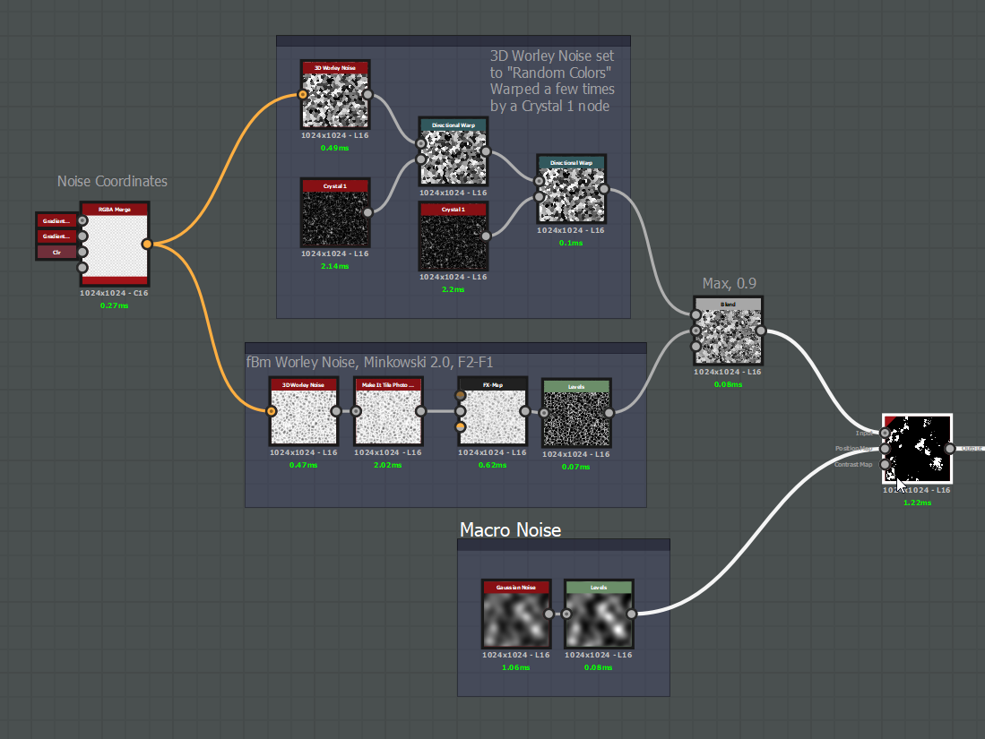
Not only does fBm noise serve well as height information - it also can act as a mask for many organic effects. In the below example i'm using Minkowski 2.0 with the F2-F1 Style and a Roughness of around 0.2 to generate an alpha decay mask.


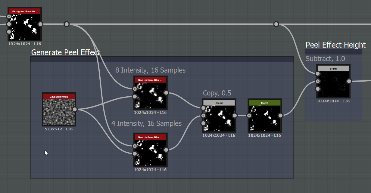
When using this mask as the base to a paint peeling effect, you can get some really cool results.


Watch this GIF on Gfycat. Discover more GIFS online at Gfycat.


Tweaking the Minkowski number, inverting the output or changing the mode of the Worley noise will give you a completely different feel. I could make a few tweaks to go from a flaky, cracked paint to a blistering, corroding paint. 

Below are a few shots of the node chain i'm using to generate the mask and the peel effect. The rest of the stuff is just boiler plate material blending, nothing too special going on. 

The take away from all of this is fBm noise is extremely useful and pretty easy to make in Substance Designer. I encourage you to try experimenting by substituting Worley 3D Noise with some other things like Gaussian Noise, or use a combination of the Shape and Splatter nodes. You'll get very detailed noise maps that you should be able to use for many, many effects.